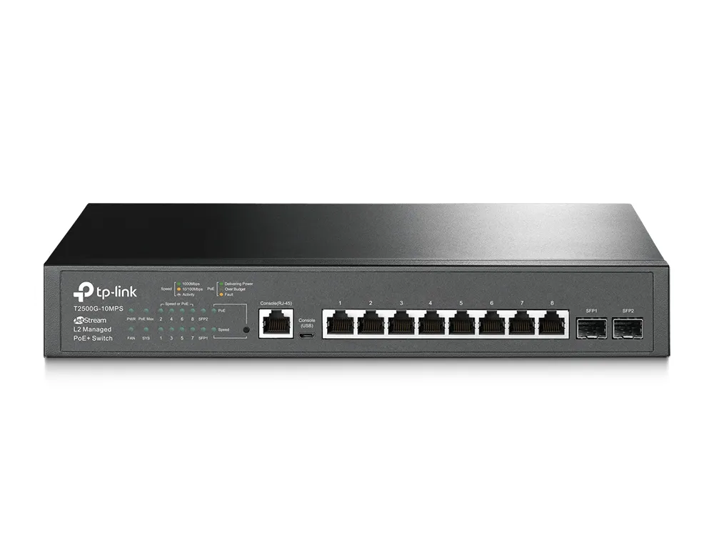
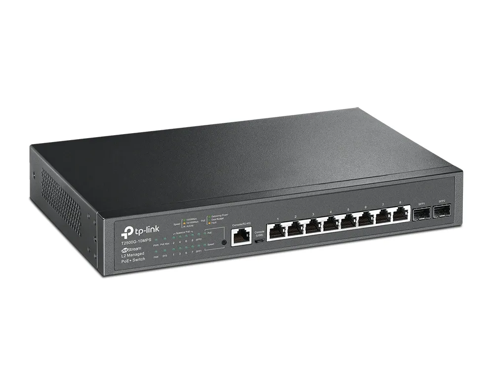
EN
TP-Link T2500G-10MPS is a managed L2 switch with eight 10/100/1000Mbps PoE ports with 116W of total power. The switch is equipped with two SFP slots, allowing to connect the main board of the device with single or multi-mode fiber optic cable. It is especially recommended for units that want to use economical solutions that guarantee gigabit data transmission in their network structure. The switch can be used in a small office, but also at home.
TP-Link T2500G-10MPS switch has reliable and functional management mechanism in the second layer. The device is perfect for connecting with other switches and servers supporting gigabit network capacity. TP-Link T2500G-10MPS is also a device providing security mechanisms of our network, with functions such as: Storm Control, port protection, broadcast storm or DHCP Snooping, IP-MAC-Port. The switch also uses a mechanism called QoS, enabling better transmission of audio, video or data in the network.
Features / filters | |
LAN standard | Gigabit Ethernet 10/100/1000 Mb/s |
Number of LAN ports | 8x [10/100/1000M (RJ45)] |
Number of PoE ports | 8x [802.3af/at (1G)] |
Built-in modem | None |
Management | Yes |
Numbers of pieces in the package | 1-pack |
Power (W) | 116 |
Switching layer | 2 |
Type of case | Desktop |
Equipment features | |
Ports | 8 PoE+ RJ45 ports 10/100/1000Mbps 2 SFP 1000Mbps slots 1 RJ45 console port 1 Micro USB console port |
Standards and protocols | IEEE 802.3i, IEEE 802.3u, IEEE 802.3ab, IEEE802.3z, IEEE 802.3ad, IEEE 802.3x, IEEE 802.1d, IEEE 802.1s, IEEE 802.1w, IEEE 802.1q, IEEE 802.1x, IEEE 802.1p, IEEE 802.3af, IEEE 802.3at |
Network cabling | 10BASE-T: Cat 3, 4 or 5 UTP cable (up to 100m) 100BASE-TX/1000Base-T: UTP cable cat 5, 5e or higher up to 100m |
Fanless | No, 1 fan |
Power supply | 100~240VAC, 50/60Hz |
PoE Budget | 116W |
Dimensions (S x G x W) | 294 × 180 × 44 mm (11,6 × 7,1 × 1,7 inches) |
Installation | For mounting in a cabinet |
Performance | |
Switching capacity | 20Gb/s |
Packet forwarding rate | 14.9Mp/s |
MAC address table | 8K |
Package buffer | 4Mb |
Jumbo frames | 10KB |
Software functions | |
Quality of Service function | Prioritization of CoS/DSCP traffic based on the IEEE 802.1p standard 8 queues Setting the queue of priorities: SP, WRR, SP+WRR Port/ data flow specific transmission limitation Voice VLAN |
Features of the layer 2 switch | IGMP Snooping V1/V2/V3 MLD v1/v2 Snooping 802.3ad LACP (Up to 8 groups, 8 ports per group) STP/RSTP/MSTP Isolation of ports BPDU filtering/protection TC/Root Protect Loopback detection Flow control 802.3x LLDP/LLDP-MED DHCP VLAN Relay L2PT |
VLANs | Up to 4096 VLAN (4096 VLAN identifiers) MAC/Protocol VLAN GARP/GVRP VLAN VPN (QinQ) Management VLAN |
Access control lists | Packet filtering L2~L4 based on source and destination MAC addresses, IP address, TCP/UDP ports, 802.1p, DSCP, protocol and VLAN ID Limited in time |
Transmission security | IP-MAC-Port-VID binding AAA DHCP Snooping IEEE 802.1X (Radius) based authentication: depending on port, MAC address, VLAN assignment Protection against DoS attacks Dynamic protection against ARP (DAI) attacks SSH v1/v2 SSL v2/v3/TLSv1 Port security Broadcast/Multicast/Unknown-unicast Storm Control PPPoE |
IPv6 | Dual IPv4/IPv6 stack MLD Snooping IPv6 ND MTU detection ICMPv6 TCPv6/UDPv6 |
IPv6 applications | DHCPv6 customer Ping6 Tracert6 Telnet(v6) IPv6 SNMP IPv6 SSH IPv6 SSL Http/Https IPv6 TFTP |
Management | GUI browser interface, CLI command line interface SNMP v1/v2c/v3, compatible with TP-LINK public and private MIB libraries RMON (groups 1, 2, 3, 9) DHCP and BOOTP customer, DHCP Snooping, DHCP Option82 Dual Image CPU monitoring Port Mirroring SNTP time synchronization MRL/NTDP Firmware update: via TFTP protocol and web browser Diagnostics: VCT test System logos, MIB public libraries |
Other | |
Certificates | CE, FCC, RoHS |
Package contents | Switch Power Cable Quick Installation Guide CD Mounting elements Rubber coasters Console cable |
System requirements | Microsoft® Windows® XP, Vista™, 7, 8, 10, MAC® OS, NetWare®, UNIX® or Linux. |
Working environment | Operating temperature: 0℃~40℃ (32℉~104℉); Storage temperature: -40℃~70℃ (-40℉~158℉) Operating humidity: 10%~90%, non-condensing Storage humidity: 5%~90%, non-condensing |
Installation instructions TL-T2500G | Download |
Introduction
Voice traffic is usually more time sensitive and may be more affected by packet loss than data traffic. You can configure Voice VLAN to optimize the transmission of voice traffic. Voice VLAN can change the priority of 802.1p voice packets and transmit packets in the desired VLAN.
Network requirements
As shown in the figure below, two IP phones are connected to port 1/0/1 and port 1/0/2 of the switch. The PC is connected to port 1/0/3 of the switch. The switch is connected to the Internet through a router via port 1/0/4. IP phones transmit voice traffic while the computer transmits data traffic. Voice traffic requires higher priority than data traffic.
Configuration diagram
To implement this requirement, you can configure it as follows:
1) Create a VLAN 2 and add port 1/0/1, port 1/0/2 and port 1/0/4 to your VLAN.
2) Configure VLAN 2 as Voice VLAN and set the voice traffic priority to 7.
3) Switch on the Voice VLAN on ports 1/0/1 and 1/0/2.
Configuration steps
For the T2600G-28TS, the following sections describe the configuration procedure.
Step 1
Select the L2 FUNCTIONS> VLAN> 802.1Q VLAN> VLAN Configuration menu and click Add to load the next page. Create a VLAN 2 for voice traffic. Enter the name of the VLAN as Voice_VLAN . There is no need to add ports that are connected to IP phones. Just add the uplink port 1/0/4 to your VLAN 2, for example, set it here as an un-tagged port. Click Create .
Step 2
Select the QoS> Voice VLAN> Global Config menu to load the next page. Enable Voice VLAN globally. Set the VLAN ID to 2 and set the priority to 7 . Click Apply .
Step 3
Select the QoS> Voice VLAN> Config Port menu to load the next page. Enable Voice VLAN on ports 1/0/1 and 1/0/2. Click Apply .
Step 4
Select the QoS> Voice VLAN> OUI Config menu to load the next page. Check the OUI table. Make sure that the OUI address of the voice device is in this table. If the source MAC address of the packet matches the OUI address in the OUI list, the switch identifies the packet as a voice packet and processes it based on the voice VLAN configuration.
The console's asynchronous serial port allows devices to be connected to the management console.
Connect the console cable switch to the main computer.
Note: The switch is off.
Step 1 Open Hyper Terminal.
Choose Start -> All Programs -> Accessories -> Communications -> Hyper Terminal.
Step 2 Create a new connection (e.g. TPLINK) and press OK.
Step 3 Select the serial port that will be used to connect the console to the switch (e.g. COM1).
Step 4
Specify the properties of the COM1 port and press OK.
Bits for a second:
38400 for TL-SG3109, TL-SL3452, TL-SL3428;
9600 for TL-SG5426, TL-SL5428, TL-SL5428E.
Data bits: 8
Parity: None
Alloy bits: 1
Flow control : None
Step 5 Turn the switch on and press the Enter button. The Hyper Terminal window will appear (see below).
It is possible to configure the switch via the console port.
WARNING:
Windows 7 and Vista do not have Hyper Terminal. Its module can be copied from the XP system: Copy hypertrm.dll and hypertrm.exe files from the computer on which the XP system is installed and upload them to the computer with Win 7 or Vista. Run hypertrm.exe program. Then you can perform the configuration described in this article.