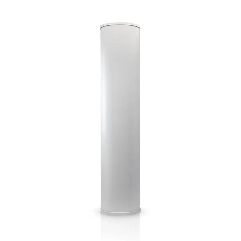
Ubiquiti AM-9M13-120 | Sector antenna | airMAX 900MHz, 13dBi
Gabaryt
Information on the person responsible for the product and safety, compliance and warnings.
DetailsRecommended products
Last seen
Information on the person responsible for the product and safety, compliance and warnings.
Details


