-
-
- Kitchen accessories
- Breathalyzers
- Blenders, mixers and planetary robots
- Electric kettles
- Coffee machines and coffee
- Waffle makers
- Frytownice (Air Fryer)
- Ice makers
- Microwaves
- Ovens and stoves
- Pressure cookers
- Soda makers
- Toasters, sandwich makers, electric grills
- Thermoses and thermal mugs
- Kitchen scales
- Irons and steamers
- Heaters
- Air treatment
- Fans and air conditioners
- Vacuum cleaners
-
- Locators
- Warranties and digital licenses
- Consoles and accessories
- Gsm accessories
- Cctv monitoring
- Tablets and e-book readers
- Photography
-
Network equipment
- Voip
- LTE, 5G
- Cables and patch cords
- Rack cabinet accessories
- Olt and ont
- Network accessories
- Wi-Fi / LTE antennas
- Enclosures, splices, boxes
- Rack cabinets
- Fiber optic welders and tools
- Access points
- Switches
- Uchwyty i akcesoria montażowe
- Sfp modules
- Power supply
- Wi-Fi signal boosters
- Routers
- Radio lines
- Powerline
- Cable pulling pilots
- Media converters
- Computers and gaming
- Drones and accessories
- Power supply
- Smart glasses
- Liczarki do pieniędzy
-
- Nasal aspirators
- Inhalers
- Lamps, star projectors
- Pregnancy pillows
- Bottle warmers
- Bottle sterilizers
- Children's thermometers
- Potty chairs and seats
- Lactation massagers
- Children's room
- Toys, games and education
- Bottles, bidons and accessories
- Breast pumps and accessories
- Bathtubs and bathing accessories
- Strollers for children
- Clothing
Unifi switches - Layer3 configuration (routing)

In this tutorial, we will show in a few steps how to configure a simple Layer3 routing, based on UniFi switches. Of course, keep in mind that not all UniFi switches support hardware support for L3 routing. In our case, the configuration will be based on the UniFi USW-Pro-48-Poe switch.
Below is an overview diagram of our topology configuration.
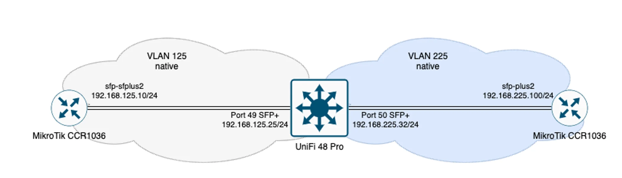
Of course, this is a conceptual configuration scheme, everything depends on the specific network topology. In our case, we're relying on two Mikrotik CCR1036-8G-2S EMs and, as I mentioned earlier, a UniFi USW-Pro-48-Poe switch.
The VLANs themselves, which we will create in our network, will be "native" to the ports they are assigned to. That is, they will handle untagged traffic relative to each other.
The VLANs themselves, which we will create in our network, will be "native" to the ports they are assigned to. That is, they will handle untagged traffic relative to each other.
UniFi OS Console configuration
So, without wasting any time, let's get on with configuring our UniFi OS Console. We will present the configuration in graphical form, which will be more readable and helpful for quick configuration.
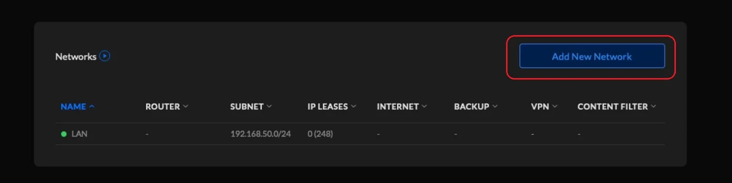
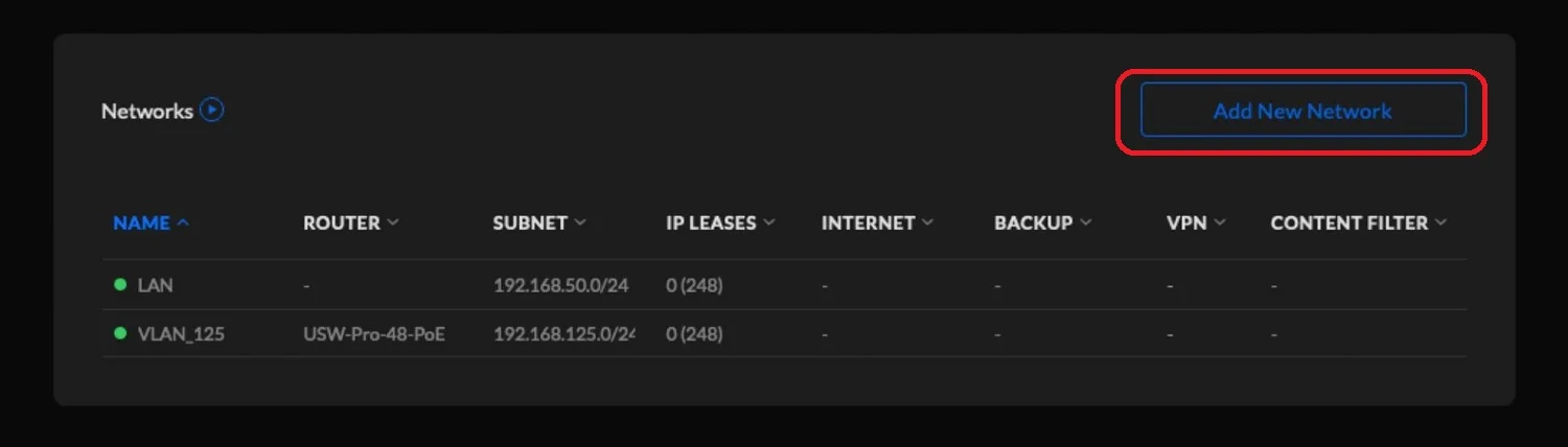
We start with the UniFi OS Console, where we create new VLAN subnets.
We start with the UniFi OS Console, where we create new VLAN subnets.
On the UniFi switch, we create a new VLAN 125
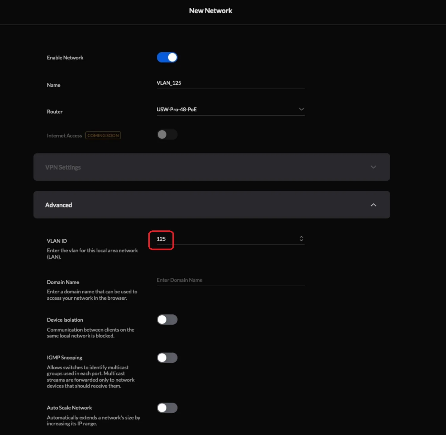
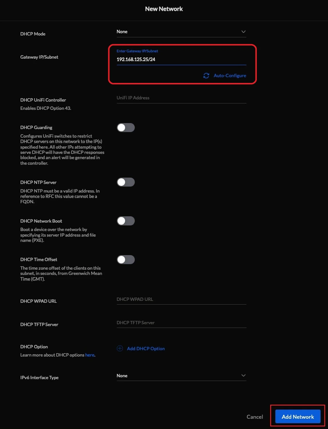
For VLAN 125 we set the default gateway, which in our case has the address 192.168.125.25
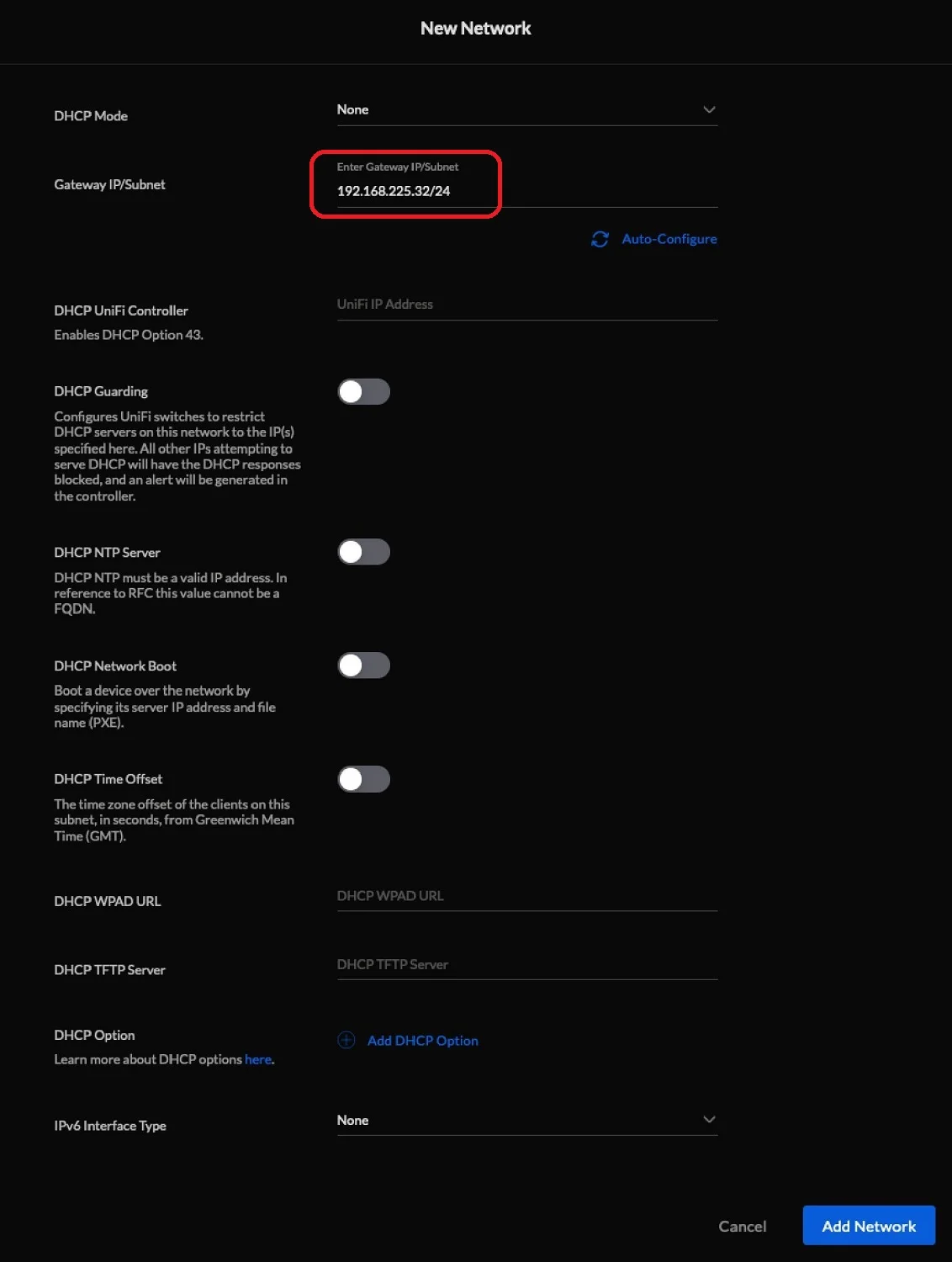
On the UniFi switch, create a second VLAN 225
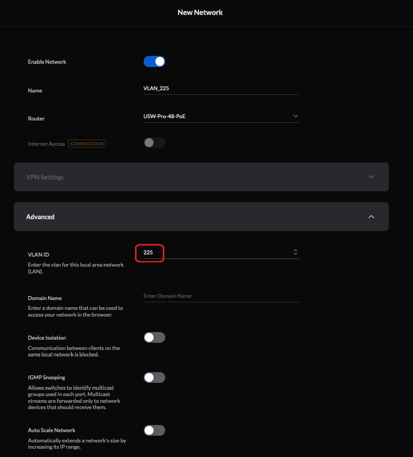
For VLAN 225, set the default gateway to 192.168.225.32
Once all the VLAN subnets are configured, the configuration on our UniFi switch should look like this:
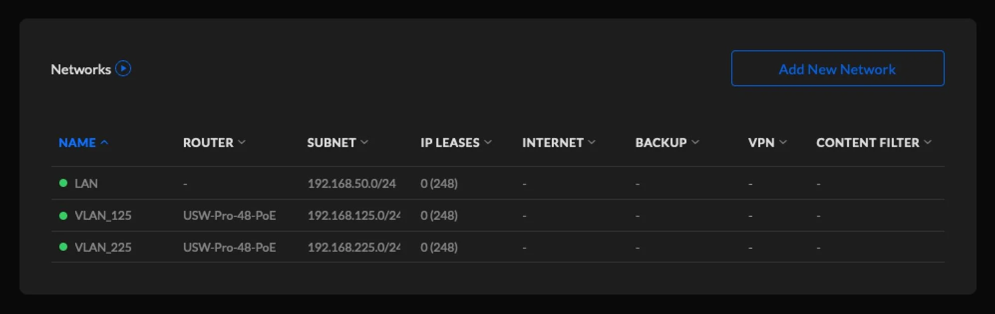
Configuration of UniFi switch
Let's move on to the actual configuration of the UniFi switch. Of course, the device must be previously adopted in our controller and updated to the latest software.
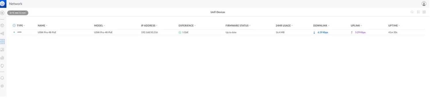
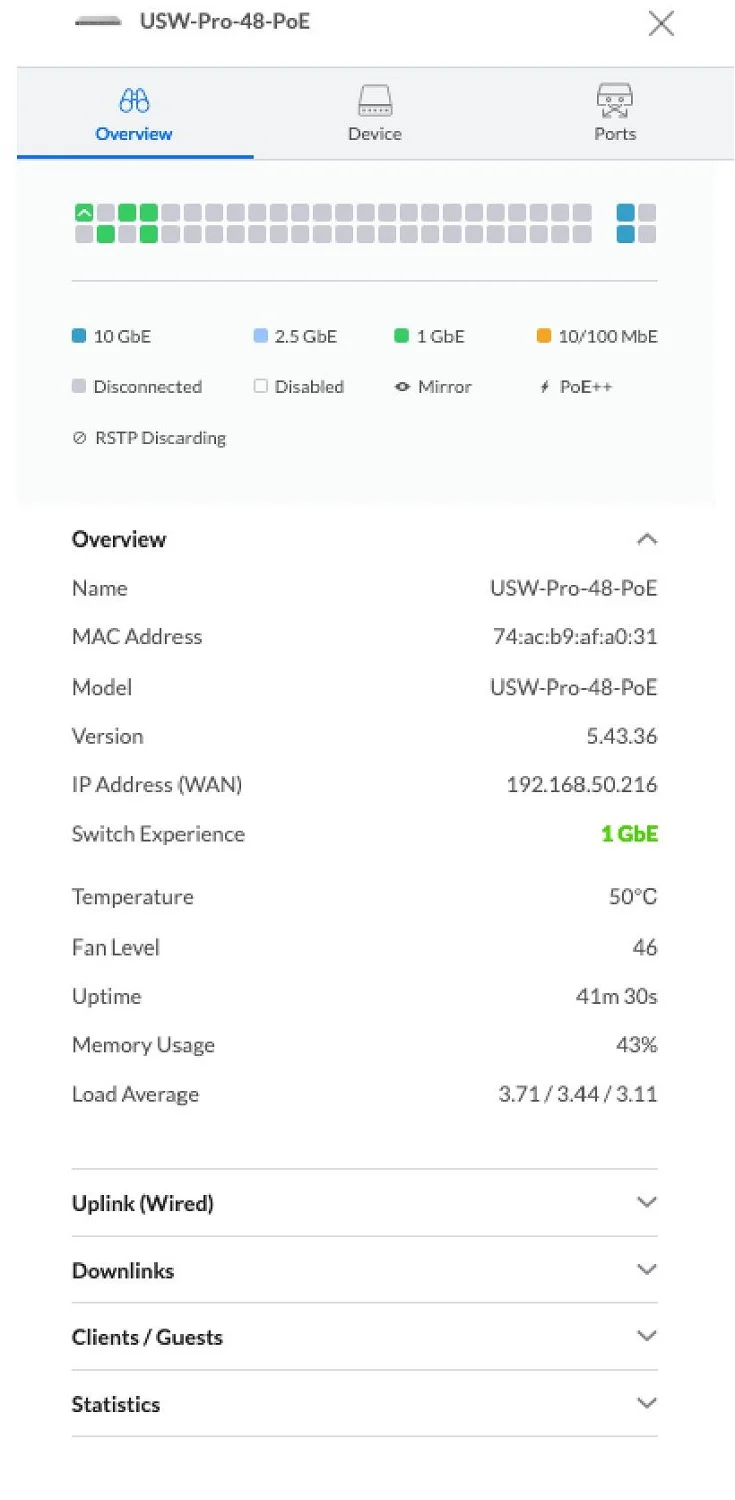
We proceed to configure the ports on our switch.
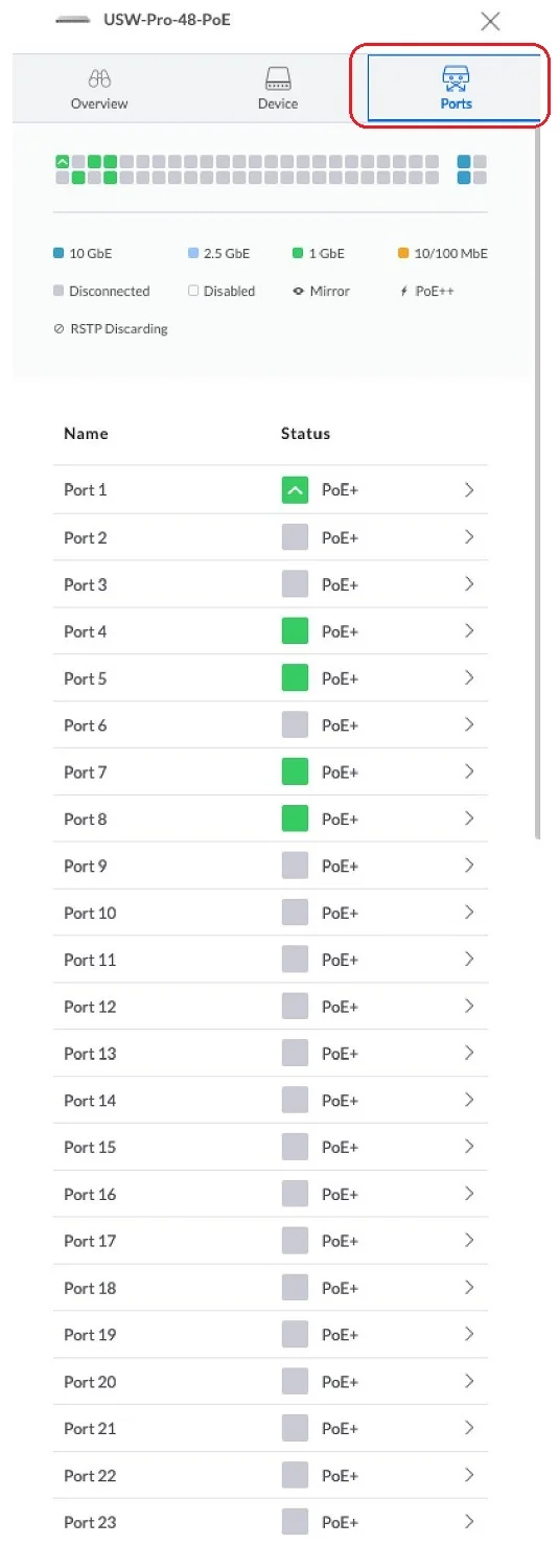
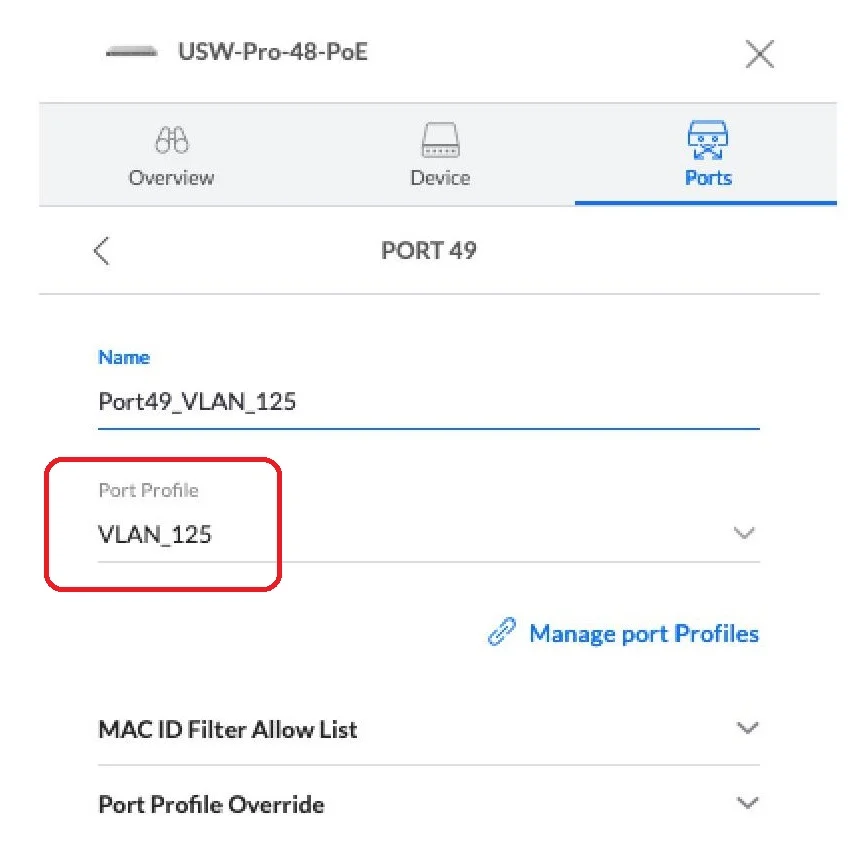
We configure port 49 of our switch for VLAN 125

Next, select the vlan profile, in our case VLAN_125, which was previously created in the controller.
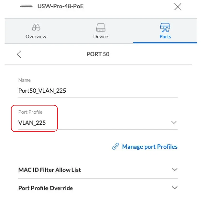
Next, we configure port 50 of our switch. Select the appropriate vlan profile VLAN_225.
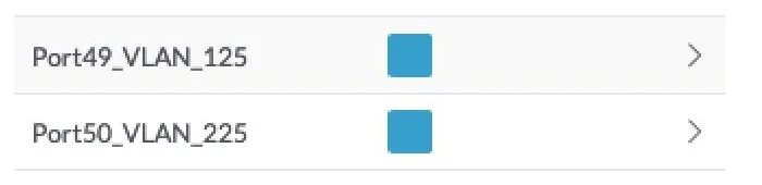
And generally, when it comes to configuring the ports on our switch, that's it. Once properly configured, ports 49 and 50 should look like this:
Configuration of Mikrotik CCR1036
As you can see, configuring the Unifi switch didn't require much effort. However, to demonstrate that our routing is properly configured and that it works at all, we will configure two CCR1036 Mikrotiks. According to our scheme, we will configure the "RIGHT" and "LEFT" Mikrotiks in order.
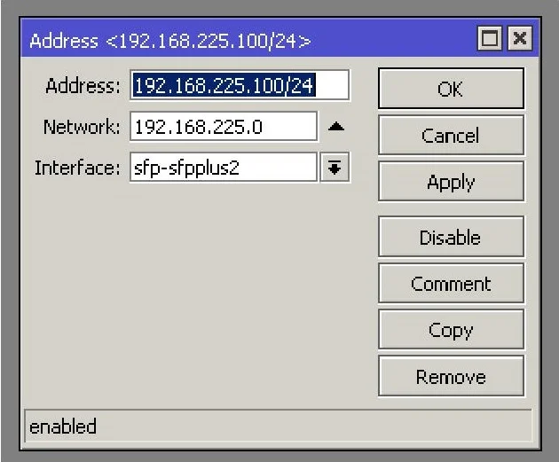
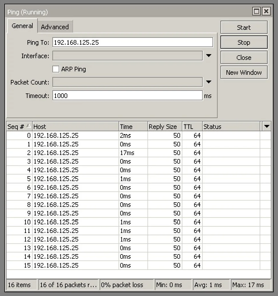
"RIGHT" Mikrotik is configured as follows:
"RIGHT" Mikrotik is configured as follows:
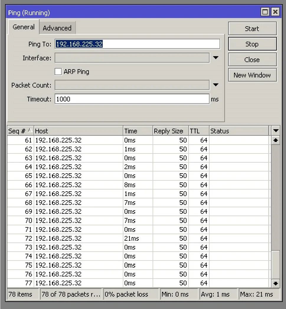
And it can ping the IP address assigned to port 50 of our UniFi switch.
The " LEFT" Mikrotik, on the other hand, has the following configuration:
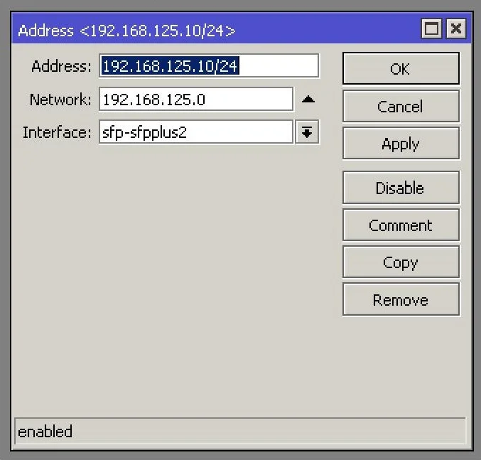
And of course, it can ping the IP address assigned to port 49 of our UniFi switch.
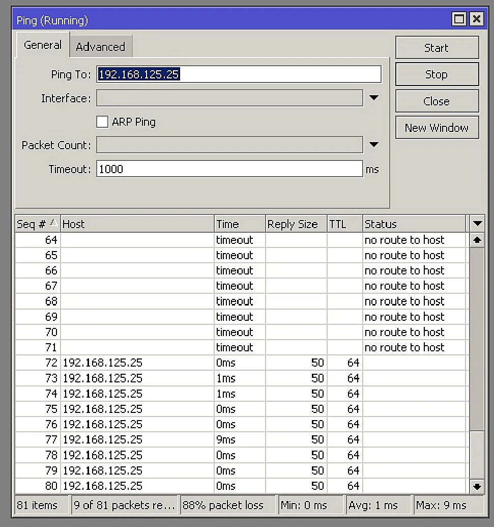
At the moment, both CCR1036, "LEFT" and "RIGHT" cannot see each other. So we have to set correct routing rules for the Mikrotik, and exactly the right network gateway .
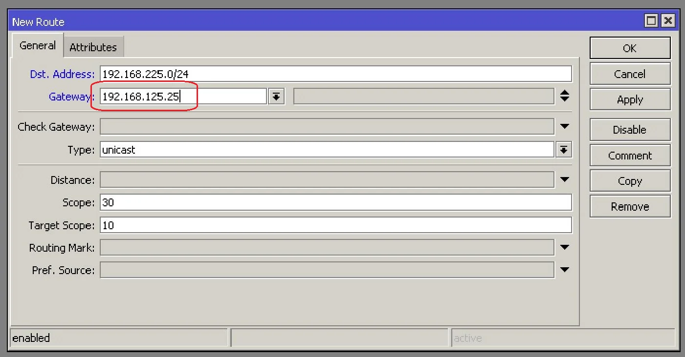
- The CCR1036 "LEFT" microticket (relative to the network diagram) - we set the gateway to VLAN_225 to the IP address assigned to port 49 of the UniFi switch
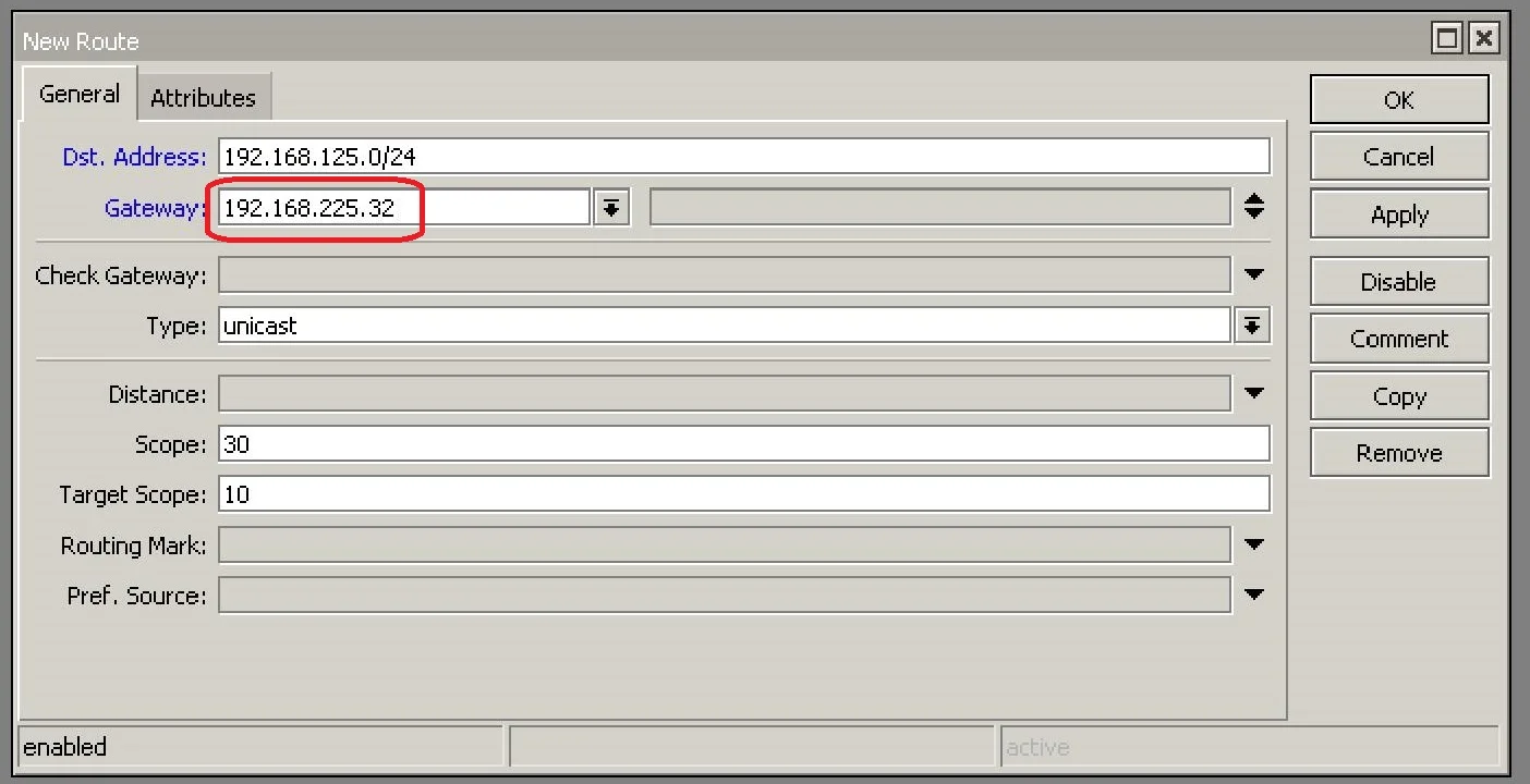
- Mikrotik CCR1036 "RIGHT" (relative to the network diagram) - set the gateway to VLAN_125 to the IP address assigned to port 50 of the UniFi switch
And only now, after entering correct gateways on our Mikrotiks, we were able to set up correct transmission.
Performance Check
Success! The transmission has been successfully put together! But... it is worth checking what kind of communication we have between the devices. I think the best test is to see what kind of performance you can get between the two CCR1036. In our diagram they are labeled "LEFT" and "RIGHT". Mikrotik Bandwidth test is a perfect tool. The results below.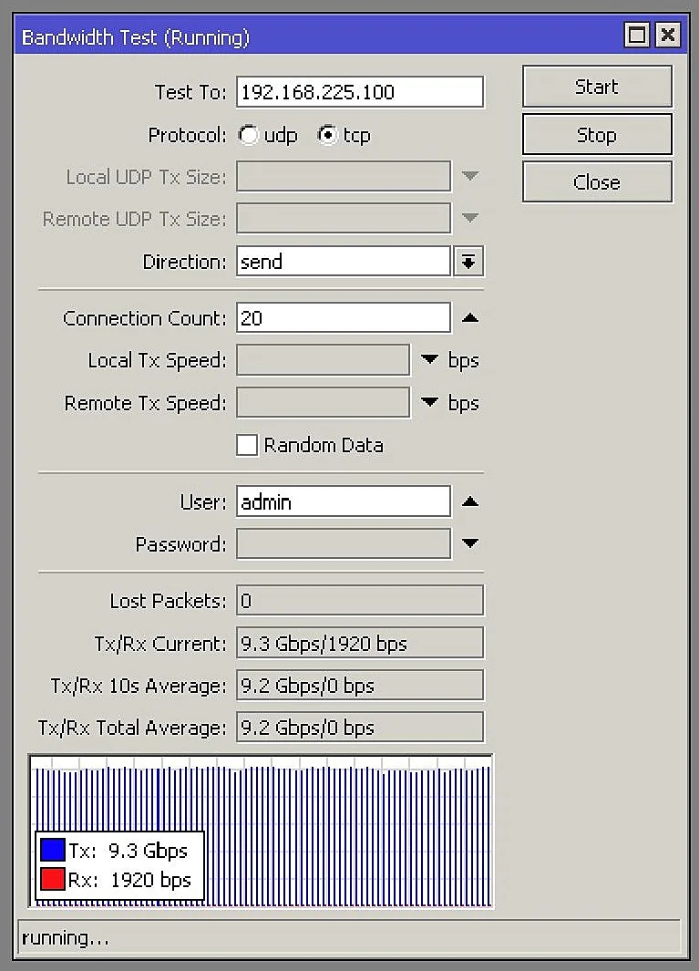
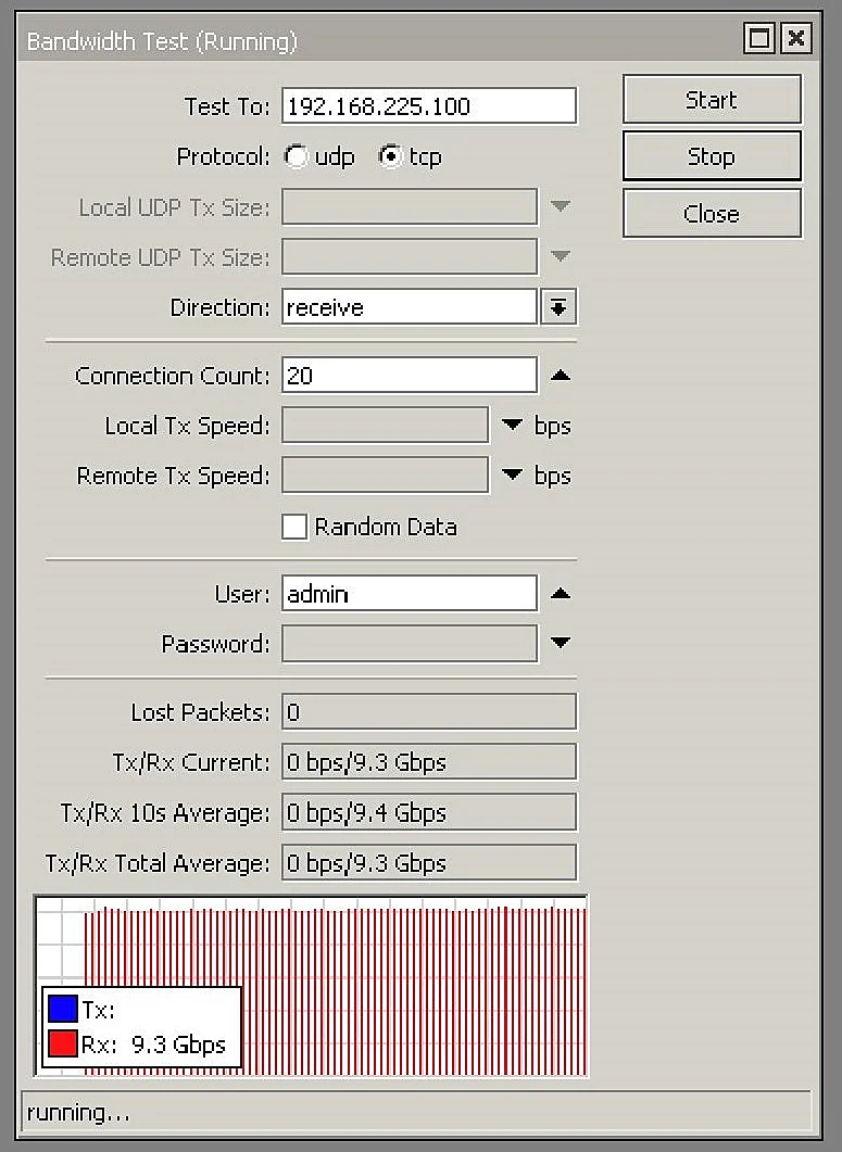
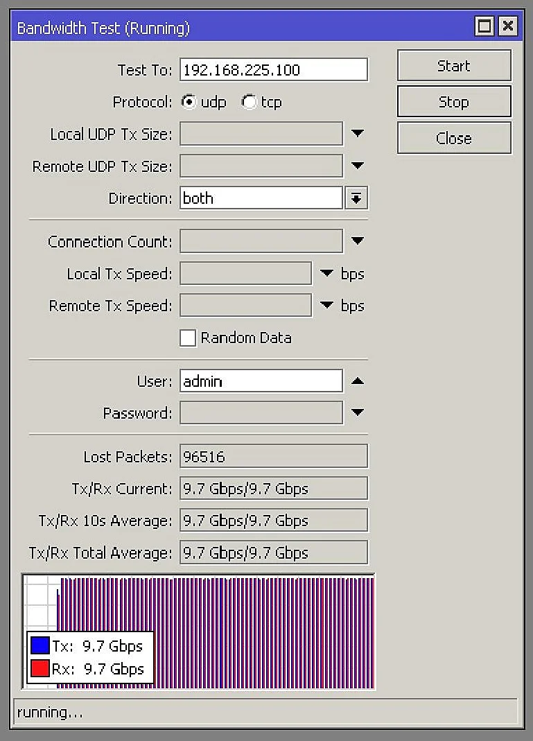
As you can see in the attached graphics, we were able to correctly configure routing on the Unifi switch. We were limited by the 10GB ports, so we got a throughput of 9.3GB each way.
To summarize. As you can see, setting up routing on the Unifi switch is trivial and anyone can do it without any problems. We invite you to comment on the article on our FB profile and on our Internet forum.
To summarize. As you can see, setting up routing on the Unifi switch is trivial and anyone can do it without any problems. We invite you to comment on the article on our FB profile and on our Internet forum.