


VLAN configuration on Mikrotik and Cisco devices

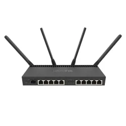
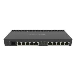
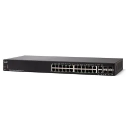
A short step-by-step guide showing how to configure VLAN networks based on Mikrotik and Cisco devices. As our main router, we will use a very powerful Mikrotik RB4011IGS+RM with a Cisco SF350-24 switch. Before we start to configure the devices, it's time for some theory.
The situation changes dramatically when we need to use more networks than just LAN and WAN. For example, if we would like to divide the network in our workplace into several sections, e.g. IT_DIVISION and ACCOUNTING, we also have a WWW server in the network and would like to access it from outside.
WAN | LAN | NAT
Our home networks are usually configured in such a way that we have one local network LAN and access to the public network through the WAN port. It is obvious that through the WAN port our ISP gives us access to the Internet. Our home router uses a mechanism for translating addresses and ports from our LAN to an external network (Internet). And this functionality is called NAT (Network Address Translation). Generally, to make such a network, a router equipped with two Ethernet ports and several switch ports is enough.The situation changes dramatically when we need to use more networks than just LAN and WAN. For example, if we would like to divide the network in our workplace into several sections, e.g. IT_DIVISION and ACCOUNTING, we also have a WWW server in the network and would like to access it from outside.
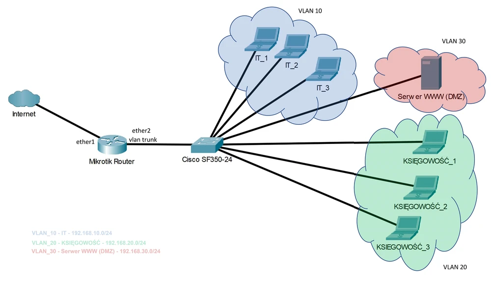
In this guide we assume the following networks:
For all subnetworks our router will assign IP addresses using DHCP_SERVER.
In this situation, there can be a big problem if our router has for example only two physical ports and we are not able to divide the network according to our assumptions. And in this situation we are helped by VLANs (Virtual Local Area Network).
- WAN - Internet access link (public address: 10.0.0.0/29)
- IT_DIVISON (address: 192).168.10.0.0/24 VLAN tag: 10)
- ACCOUNTING (address: 192.168.20.0/24 VLAN tag: 20)
- DMZ_SERVER_WWW (address: 192.168.30.0/24 VLAN tag: 30)
For all subnetworks our router will assign IP addresses using DHCP_SERVER.
In this situation, there can be a big problem if our router has for example only two physical ports and we are not able to divide the network according to our assumptions. And in this situation we are helped by VLANs (Virtual Local Area Network).
How does the VLAN work?
In short, VLAN is a mechanism that enables logical division of networks (segmentation) and aggregation of different networks (broadcast domains) within one physical port. According to this assumption, we can configure the connection between the router and the switch in such a way that several networks (ACCOUNTING, IT_DIVISION, DMZ) are available on one physical port of the router and switch. The principle of VLANs is also very simple. Every Ethernet frame receives a unique identifier called a VLAN TAG. The identifier indicates which subnet the packet belongs to. VLAN TAG is simply a number from 0 to 4096, which is assigned by the network administrator. The switch must remove the identifier on the ports to which terminal devices such as printers, telephones, IP telephones, etc. are connected. Such a port is called ACCESS. Using VLAN mechanism has many advantages:
- Less cables! We save the number of physical ports on routers and switches.
- Division into subnets makes it easier to manage the firewall policy
- With VPN you can connect multiple branches of a company that has multiple LANs
- No need to use a separate switch for each of the supported subnets.
MicroTik router configuration
Well, let's start setting up. First we will configure our main Mikrotik RB4011IGS+RM router.
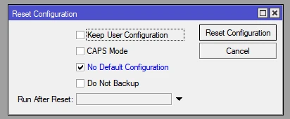
1. Reset the MikroTik to default configuration
1. Reset the MikroTik to default configuration
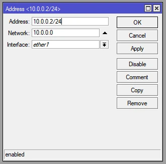
2. WAN port address (ether1)
IP address: 10.0.0.2/24
Network: 10.0.0.0/24
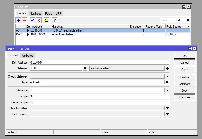
Gateway: 10.0.0.1
IP address: 10.0.0.2/24
Network: 10.0.0.0/24
Gateway: 10.0.0.1
Default gateway setting - default gateway
Configuration of VLAN interfaces on ether2 port (for each subnet)
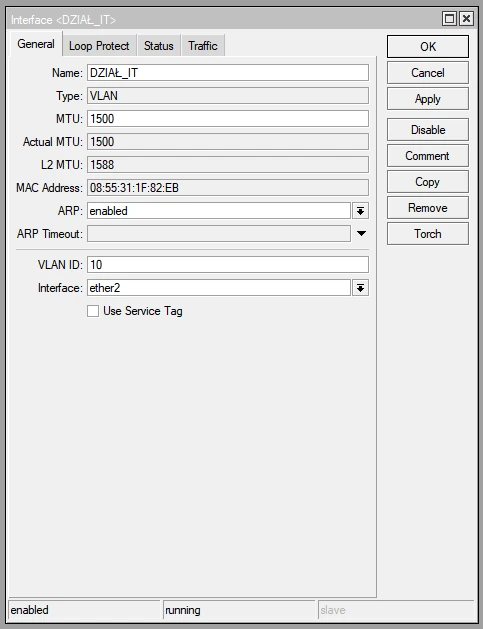
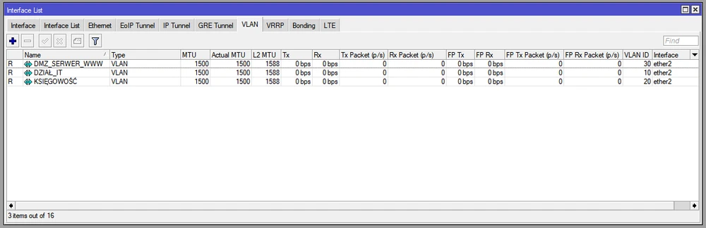
Addressing VLAN interfaces (for each network)
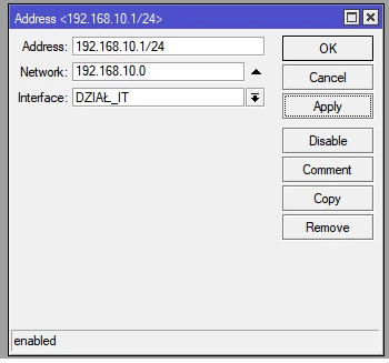
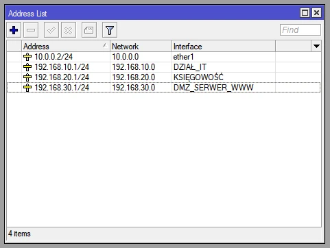
6. DHCP Server
Of course, we configure the DHCP Server in the same way as for any network: IT_DIVISION, ACCOUNTING, DMZ_SERVER_WWW.
Of course, we configure the DHCP Server in the same way as for any network: IT_DIVISION, ACCOUNTING, DMZ_SERVER_WWW.
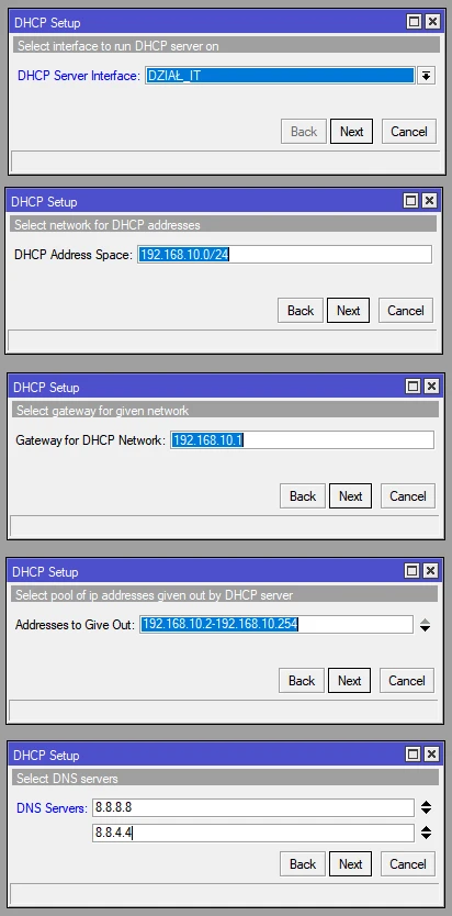
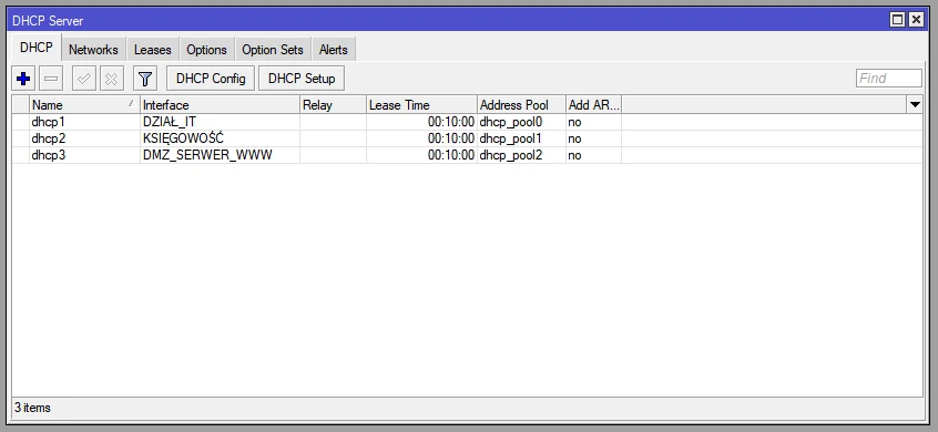
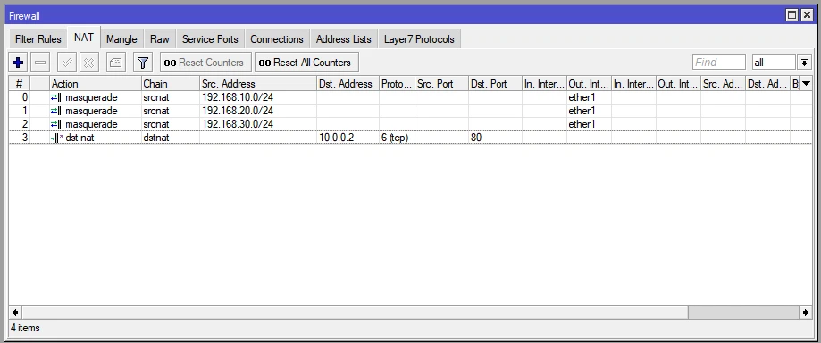
7. Set SRCNAT for all created networks.
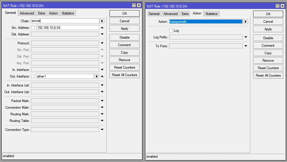
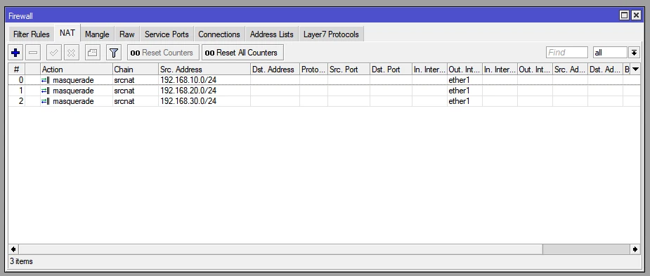
We must also not forget that we have a web server on our network that we want to have access to from outside.
For the www server we set the IP address 192.168.30.2.

Configuration of the Cisco switch
Once we've configured our router, we can now proceed to configure our switch. The configuration is based on a Cisco SF350-24 switch. 24 RJ45 ports with 100Mbps throughput, 2 Gigabit Combo (RJ45/SFP) ports and 2 SFP fiber optic ports. SF350-24 is a powerful switch; 9.52 million packets per second (with 64-byte packets) and 12.8Gb/s switching performance. This is enough to make it work in the network presented by us.
Cisco devices are invaluable! And we must admit that the configuration of a VLAN-based network on Cisco switches is trivially simple. Below in a few steps I present the configuration of VLAN networks.
WARNING! For managed Cisco 300 and 500 series switches, the bitrate must be set to 115200, while the COM port must be selected according to its connection to the computer.
Cisco devices are invaluable! And we must admit that the configuration of a VLAN-based network on Cisco switches is trivially simple. Below in a few steps I present the configuration of VLAN networks.
Configuration of ports
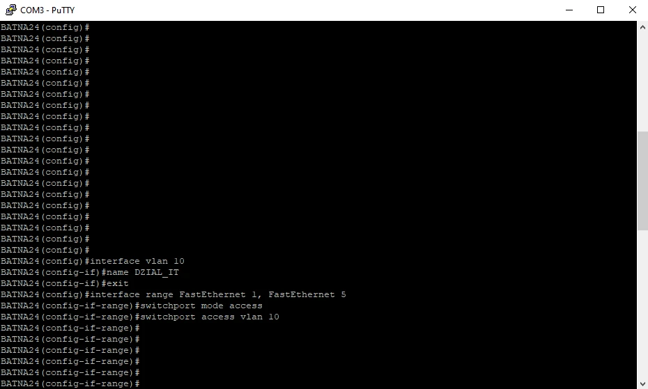
We will configure the ports on our switch as follows:- Ports 1-5 - VLAN 10 - IT_DIVISION
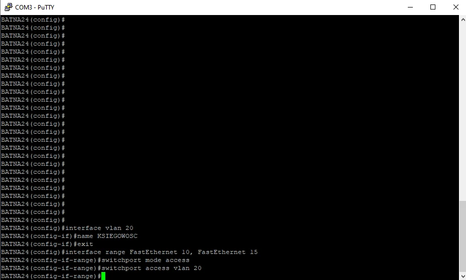
- Ports 10-15 - VLAN 20 - ACCOUNTING
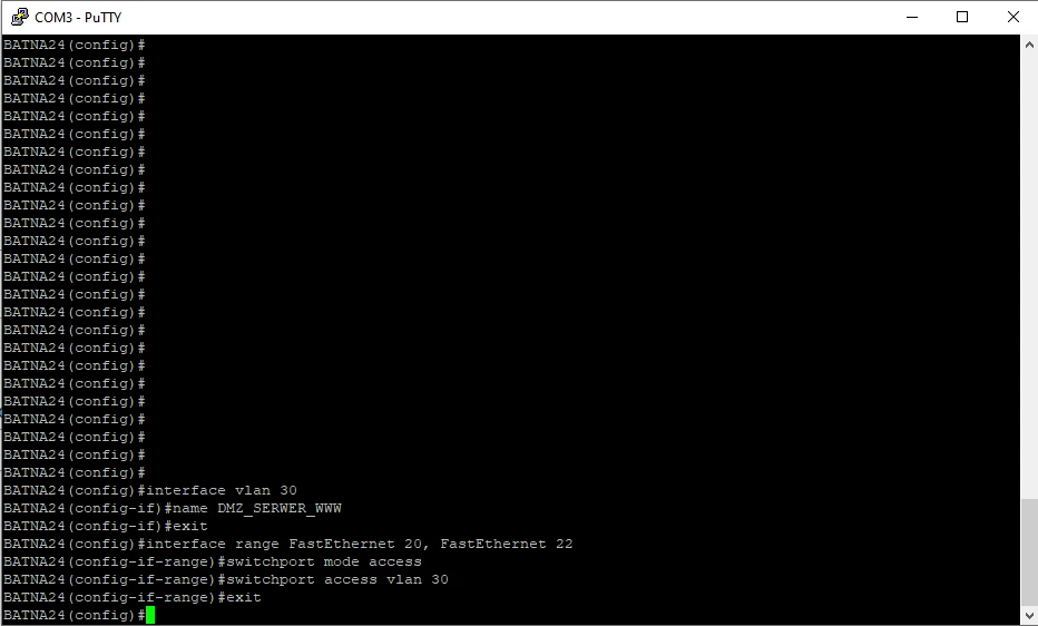
- Ports 20-22 - VLAN 30 - DMZ_SERVER_WWW
- Port 24 - TRUNK
Access to CLI through Putty
To get to the device, use the CONSOLE port, the appropriate RS323-RJ45 cable (included) and the Putty software, which of course must be properly configured.WARNING! For managed Cisco 300 and 500 series switches, the bitrate must be set to 115200, while the COM port must be selected according to its connection to the computer.
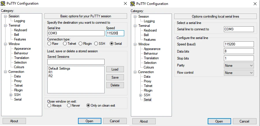
Switch configuration - VLAN
If we have configured Putty correctly, we will get on the switch. Login: cisco , password: cisco.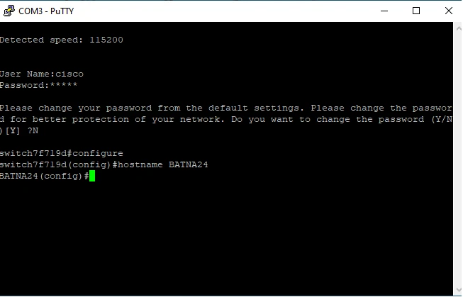
Then configure the switch ports according to the previous assumptions. We will start with TRUNK port.
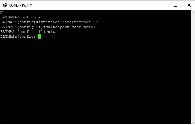
And of course all VLANs: IT_DIVISION (vlan 10); ACCOUNTING (vlan 20); DMZ_SERVER_WWW (vlan 30).
Summary
And in such a quick way we managed to configure our network with division into VLANs. The whole configuration process is really easy. Both the router and the switch have been properly configured. Of course, when configuring such a network you have to remember a few important assumptions. First of all, use very complicated passwords on each device and disable those login methods that we don't use, Telnet for example. It is also worth introducing restrictions on IP/Neighbors protocol operation.
In general, networks based on VLANs are very secure and simplify the management of the entire structure for each administrator. To build a network based on vlans we only need a layer 2 switch. Well, I hope this guide will be useful when designing LAN based on virtual LAN (VLAN). With applying some basic network design rules we are able to build a very efficient and secure LAN.
For further discussion on the subject, please visit our FORUM!!!
Author:
Leszek Błaszczyk