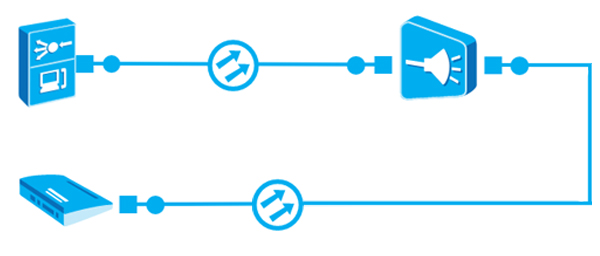
When designing a fiber optic line, it is necessary to define the maximum distance of the fiber optic path determined between the OLT unit and ONU, ONT client terminals. For this purpose, a power balance of the fiber optic line is prepared, which takes into account the power put into the line, as well as the losses on the passive elements used to build the network.


| Classes of SFP Inserts | |||
|---|---|---|---|
| B+ | C+ | C++ | |
| Output Power | 5 dBm | 7 dBm | 10 dBm |
| Sensitivity | -28 dBm | -32 dBm | -35 dBm |
The input power is the sum of the input power from the active device and the signal gain.
When calculating the losses, the attenuation of the fiber, fiber optic connectors and splices is taken into account. The total attenuation depends on the length of the fiber and the unit attenuation specified per unit length.
The unit attenuation depends on the type of fiber used to build the cable and can be found in the data sheet and depends on the wavelength at which the active devices operate. The average is 0.3dB/km
Passive splitters are used for splitting the optical fiber signal in PON networks, which are characterized by specific attenuation, depending on the degree of division. One or more splitters can be used throughout the path, but keep in mind that each additional splitter introduces additional attenuation.
| PLC Splitters | ||||||
|---|---|---|---|---|---|---|
| 1:2 | 1:4 | 1:8 | ||||
| Attenuation dB | <4.10 | <7.30 | <10.50 | |||
| PLC Splitters | ||||||
|---|---|---|---|---|---|---|
| 1:16 | 1:32 | 1:64 | ||||
| Attenuation dB | <13.60 | <16.70 | <20.20 | |||
The weld attenuation determines the degree to which the signal is attenuated when it passes through the fiber connection made by a fiber optic welding machine. Each weld has a different attenuation value that depends on the quality of the weld workmanship, but for calculations the average value is used, i.e. 0.05 dB - 0.1 dB.
Attenuation of optical connector is a parameter that describes the degree of signal attenuation when passing through a disconnected connection, i.e. the connection made with the use of an optical fiber adapter. This value depends on the class of accessories used, and for calculations is taken as 0.2 dB - 1 dB.
When calculating the budget, a certain safety margin is assumed. It is supposed to compensate future changes in parameters of components used for building the network, which are subject to aging processes and influence of temperature factors. The standard assumption is 6 dB.
Receiver sensitivity > Transmission power - Fiber attenuation - Splitter attenuation - Splice attenuation - Adapter attenuation - Safety margin
Calculation example:
Transmit power: SFP class C+ with 10 dBm
Attenuation in the path:
Power = 10dBm-(18 dB+10,5 dB+0,6 dB+1,2 dB)-6 dB = -26,3 dB
The calculations show that for proper operation of the link, the client should be connected to B+ class equipment.