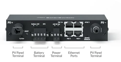
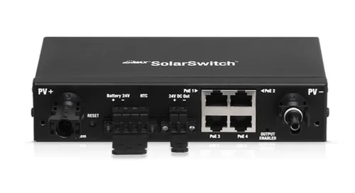
Ubiquiti SM-SW-40 | Switch | Sunmax SolarSwitch, 4x RJ45 100Mb/s PoE


EN
The SolarSwitch SM-SW-40 from Ubiquiti can be remotely managed and has maximum power monitoring (MPPT) 24 V, 7A. The device has a built-in 4-port PoE switch 24 V and DC output power up to 40 W, while modern software allows to forecast the weather.
SolarSwitch is easy to configure for almost any combination of devices.
SolarSwitch can be installed on both sides of the rack using the included mounting bracket.
Sunmax SM-SW-40 offers easy management and the user interface allows administrators to configure devices and monitor their charging.
Features / filters | |
LAN standard | Fast Ethernet 10/100Mb/s |
Number of LAN ports | 4x 10/100BaseTX (RJ45) |
Number of PoE ports | 4x [Passive PoE 24V (100M)] |
Type of case | Metal |
Basic technical parameters | |
Dimensions | 168 × 136 × 36 mm |
Weight | 543 g |
Enclosure characteristics | Steel, internal use |
Maximum power consumption | 2W |
Network interface | (4) 10/100 Fast Ethernet ports |
Management interface | Ethernet + Wi-Fi (2.4 GHz) |
Button | Reset |
LED | System, output |
Power source | PV panel (H4 connectors) |
Voltage range | 10-60 V |
Maximum current | 10A |
Power control | MPPT |
Output interfaces | 24VDC passive PoE (pins 4, 5+; 7, 8-) Terminal block 24VDC |
Output voltage | Battery voltage limited to 24 V (Surge protection) |
Maximum output power | PoE: 17W, DC output: 24W, Maximum total 40W |
Battery type | 24 V SLA, AGM, lead-gel battery |
Absorption voltage steps | 27.4 V, 28.2 V, 29.1 V, 30 V |
Float charge voltage | 95% of the voltage increase |
Maximum charge current | 7A |
Low-voltage protection | 22 - 23.6 V Configurable software 22 V Equipment protection 2 Priority levels for exit |
Operating temperature | -20 to 50° C |
Certificates | FCC/IC/CE |
Information brochure | Download |
1. Attach the 1U rackmount bracket (included) to either side of the SolarSwitch.
2. Mount the SolarSwitch to one of the side rails in your rack.
3. Remove the four-pin connector from the battery terminal block.
4. Crimp a ferrule on one end of the wire.
5. Insert the crimped wire into the appropriate slot on the four-pin connector. Using a flathead screwdriver, secure the wire to the connector by tightening the screw until it stops.
6. Repeat steps four and five until the connector is fully occupied with all four wires.
7. Attach the NTC and battery cable using the four-pin connector.
8. Attach the PV panel cables.
Operating temperature: -20 to 50° C
4x PoE [Passive PoE 24V (100M)]